### Working Principle
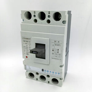
Electronic current adjustable circuit breakers are usually composed of current transformers, self-powered power supply circuits, data processing circuits, control units and actuators. The current transformer is connected in series to the working line to sense the load current in real time and convert the current signal into an electrical signal that can be processed by the electronic circuit board assembly. The electronic circuit board assembly processes the current signal, including amplification, filtering and other operations, and then compares, analyzes and calculates it with the pre-set current threshold. When the processed current signal reaches or exceeds the set value, the electronic circuit board assembly will drive the release to disconnect the moving and static contacts of the circuit breaker, cut off the circuit, and realize overload protection and other functions.
### Features and Advantages
– **High-precision current detection**:
The use of electronic technology and intelligent algorithms can accurately measure the current in the circuit with high measurement accuracy and relatively little influence by ambient temperature.
– **Rich protection functions**:
It has many protection functions such as long-delay inverse time protection, short-delay inverse time protection, short-circuit instantaneous protection, ground fault protection, etc., and can be equipped with communication to realize the “four remote” functions of remote signaling, remote control, remote measurement, and remote adjustment. It also has additional functions such as thermal memory, pre-alarm, and fault query.
– **Adjustable current**:
According to the actual circuit load conditions, the protection value can be easily set to achieve precise control and protection of different current values.
– **Remote monitoring and management**:
It integrates remote operation and monitoring functions, and can transmit equipment status, location, opening and closing instructions and other information in real time, providing managers with convenient remote management methods, improving management efficiency, and reducing operation and maintenance costs.
### Application scenarios
– **Industrial field**:
In the power distribution system of the factory, it is used to protect various electrical equipment such as motors, transformers, and production lines to ensure the stable operation of industrial production. For example, in the automated production line of new energy vehicle manufacturing, it can provide high-precision current protection for key equipment such as battery test benches and precision assembly robots.
– **Commercial field**:
Applicable to commercial places such as shopping malls, hotels, office buildings, etc., to protect various electrical equipment such as lighting equipment, air conditioning systems, elevators, etc. in their electrical systems, and prevent electrical accidents caused by overload, short circuit and other faults.
– **Family residence**:
It can be used to protect household circuits, prevent overload, short circuit and other problems caused by improper use of electrical appliances or circuit failures, ensure the safety of household electricity use, and can also be combined with smart home systems to realize intelligent power management.
– **Other fields**:
In some places with high requirements for power supply stability and safety, such as hospitals, data centers, transportation hubs, etc., electronic current adjustable circuit breakers have also been widely used to provide reliable power protection for key equipment in these places.
Basic Working Principle
**Electromagnetic Induction**: When the circuit is normal, the current passing through the air circuit breaker generates a certain magnetic field. The magnetic field generated by the normal current is not enough to cause the movement of the magnetic system in the circuit breaker. However, when a fault occurs and the current suddenly increases sharply, according to Ampere’s law, the increased current will generate a much stronger magnetic field.
**Thermal Effect**: In addition to the electromagnetic effect, the thermal effect also plays an important role. When an overcurrent passes through the conductor of the air circuit breaker, according to Joule’s law, the conductor will generate heat due to the resistance. The heat generated is proportional to the square of the current, the resistance of the conductor and the time. Under normal current conditions, the heat generated is within a tolerable range and will not cause the air circuit breaker to trip. But when an overcurrent occurs, the heat generated rapidly increases.
### Tripping Mechanism
**Electromagnetic Tripping**: The increased magnetic field due to the overcurrent causes the armature in the electromagnetic tripping device to be attracted, and the armature drives the tripping mechanism to move, disconnecting the circuit breaker’s contacts and cutting off the circuit. This is mainly used to protect against short-circuit faults, where the current increases instantaneously and significantly.
**Thermal Tripping**: The excessive heat generated by the overcurrent causes the bimetallic strip in the thermal tripping device to deform. The bimetallic strip is composed of two different metals with different coefficients of thermal expansion. When heated, the two metals expand at different rates, causing the bimetallic strip to bend. As the temperature rises due to the overcurrent, the bimetallic strip bends to a certain extent and pushes the tripping mechanism to trip the circuit breaker. This is mainly used to protect against overload faults, where the current is larger than the rated current but not as extreme as in a short circuit, and the overcurrent lasts for a certain period of time.
### Arc Extinction Mechanism
**Arc Generation**: When the contacts of the air circuit breaker are disconnected, an arc is generated between the contacts due to the ionization of the air and the high temperature. The arc can conduct electricity and may cause damage to the contacts and other components if it is not extinguished in time.
**Arc Extinction Principle**: Air circuit breakers usually use measures such as lengthening the arc, cooling the arc and blowing out the arc to extinguish the arc. For example, some air circuit breakers are equipped with arc extinguishing chambers. The arc extinguishing chamber is usually made of materials with good insulation and heat dissipation performance. When the arc enters the arc extinguishing chamber, it is lengthened and cooled by the baffles and grooves in the chamber. At the same time, the air flow generated by the movement of the contacts can also blow out the arc, so that the arc is quickly extinguished and the circuit is completely disconnected.
In general, Chinese air circuit breakers use a combination of electromagnetic, thermal and arc extinguishing principles to achieve the functions of overcurrent protection and circuit disconnection, ensuring the safety and stability of the power system.
]]>
Version 1.0.0
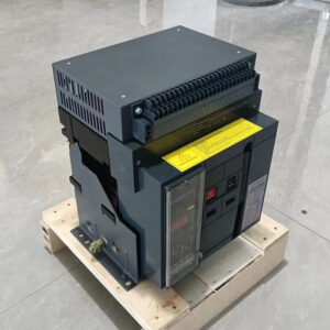
Components of an Air Circuit Breaker
Operating Mechanism: This mechanism is responsible for opening and closing the circuit breaker contacts. It can be manual, electrically operated, or motorized.
*?Contacts: ACBs have main contacts that make or break the electrical circuit. These contacts are usually made of high-conductivity materials to ensure efficient current flow.
*?Arc Chute: When the contacts separate during the circuit interruption process, an arc forms due to the ionization of air. The arc chute is designed to quickly extinguish this arc by creating a series of arc paths with increasing length, thus facilitating rapid cooling and deionization of the air.
*?Trip Unit: The trip unit detects abnormal electrical conditions such as overcurrent, short circuit, or earth fault. It initiates the opening of the contacts to interrupt the current flow when such faults occur. The trip unit can be thermal, magnetic, or a combination of both.
*?Operating Handle or Control Panel: This component provides the means for manual operation of the ACB. In some cases, it may also include control panels for remote operation and monitoring.
*?Enclosure: The ACB is housed within an enclosure to protect it from environmental factors such as dust, moisture, and accidental contact. The enclosure also provides insulation and safety for maintenance personnel.
*?Mechanical Interlocks: These safety features prevent the ACB from being operated under unsafe conditions, such as when the contacts are engaged or when the breaker is in a test position.
*?Trip Indication: ACBs often include indicators to show when the breaker has tripped due to an abnormal condition. This helps in troubleshooting and maintenance.
*?Auxiliary Contacts: These contacts are used for signaling and control purposes, such as indicating the status of the circuit breaker (open or closed) or providing feedback to control systems.
*?Closing and Opening Coils (for electrically operated/motorized mechanisms): In electrically operated or motorized ACBs, coils are used to generate magnetic forces that aid in the opening and closing of the contacts.
These components work together to provide reliable and efficient protection for electrical circuits against overloads, short circuits, and other faults.
2.Application:
In residential applications, three-phase contactors are widely used, especially in large and office buildings. These structures typically house various electrical equipment and motors, including air conditioners, elevators, water pumps, and generators. Precise control of these motors is essential to ensure their smooth operation at all times. The three-phase contactor achieves this by opening or closing the motor as needed, optimizing energy utilization. This not only reduces energy costs but also extends the motor’s lifespan, minimizing maintenance expenses. Furthermore, in building development, three-phase contactors can be used to control the operation of components such as elevators and automatic doors, ensuring their normal functioning and customer safety.
3.How to use three-phase contactors correctly?
Proper use of three-phase contactors is crucial for their long-term reliability and stability. Firstly, before using a three-phase contactor, it’s essential to ensure that the motor and load parameters comply with the contactor’s specifications and capacity. Exceeding the capacity can lead to overheating, damage, or even fire. Secondly, when using a three-phase contactor, it’s important to ensure a stable and high-quality power supply. Unstable power or low voltage can result in contactor burning or failure. Therefore, a thorough check and testing of the power supply must be conducted before using the three-phase contactor to ensure its quality and stability meet the requirements. Regular inspections and maintenance of the contactor, including cleaning relays and contacts, checking for damage or deformation of the contactor housing, and verifying the normal connection of circuits, can ensure its long-term stable operation.
4.In conclusion
The three-phase contactor, as a core device in the field of electrical automation, has become a crucial tool in modern industry and construction. In residential applications, it not only reduces energy costs but also ensures the normal operation of components such as motors and automatic doors, guaranteeing the safety of buildings and occupants. When using a three-phase contactor, attention must be paid to ensuring the stability and compliance of the load and power supply requirements for long-term reliability and stability.
Voltage Rating
The overall voltage rating is calculated by the highest voltage that can be applied across all end ports, the distribution type and how the circuit breaker is directly integrated into the system. It is important to select a circuit breaker with enough voltage capacity to meet the end application.
Circuit breakers up to 600 amps can be applied to frequencies of 50-120 Hz. Higher than 120 Hz frequencies will end up with the breaker having to derate. During higher frequency projects, the eddy currents and iron losses causes greater heating within the thermal trip components thus requiring the breaker to be derated or specifically calibrated. The total quantity of deration depends on the ampere rating, frame size as well as the current frequency. A general rule of thumb is the higher the ampere rating in a specific frame size the greater the derating needed. All higher rated breakers over 600 amps contain a transformer-heated bimetal and are suitable for 60 Hz AC maximum. For 50 Hz AC minimum applications special calibration is generally available. Solid state trip breakers are pre-calibrated for 50 Hz or 60 Hz applications. If doing a diesel generator project the frequency will either be 50 Hz or 60 Hz. It is best to check ahead of time with an electrical contractor to make sure calibration measures are in place before moving forward with a 50 Hz project.
Maximum Interrupting Capacity
The interrupting rating is generally accepted as the highest amount of fault current the breaker Control Panel Circuit Breakerscan interrupt without causing system failure to itself. Determining the maximum amount of fault current supplied by a system can be calculated at any given time. The one infallible rule that must be followed when applying the correct circuit breaker is that the interrupting capacity of the breaker must be equal or greater than the amount of fault current that can be delivered at the point in the system where the breaker is applied. Failure to apply the correct amount of interrupting capacity will result in damage to the breaker.
Continuous Current Rating
In regards to continuous current rating, molded case circuit breakers are rated in amperes at a specific ambient temperature. This ampere rating is the continuous current the breaker will carry in the ambient temperature where it was calibrated. A general rule of thumb for circuit breaker manufactures is to calibrate their standard breakers at 104° F. Ampere rating for any standard application depends solely on the type of load and duty cycle. Ampere rating is governed by the National Electrical Code (NEC) and is the primary source for information about load cycles in the electrical contracting industry. For example lighting and feeder circuits usually require a circuit breaker rated in accordance with the conductor current carrying capacity. To find various standard breaker current ratings for different size conductors and the permissible loads consult NEC table 210.24.
Atypical Operating Conditions
When selecting a circuit breaker it is crucial to have in mind the end user location. Each breaker is different and some are better suited for more unforgiving environments. Below are a few scenarios to keep in mind when determining what circuit breaker to use:Weather Proof Control Panels Protect Components
? High Ambient Temperature: If standard thermal magnetic breakers are applied in temperatures exceeding 104° F, the breaker must be derated or recalibrated to the environment. For many years, all breakers were calibrated for 77° F which meant that all breakers above this temperature had to be derated. Realistically, most enclosures were around 104° F; a common special breaker was used for these types of situations. In the mid-1960s industry standards were changed to make all standard breakers be calibrated with 104° F temperature in mind. ? Corrosion and Moisture: In environments where moisture is constant a special moisture treatment is recommended for breakers. This treatment helps resist mold and/or fungus that can corrode the unit. In atmospheres where high humidity is prevalent the best solution is the usage of space heaters in the enclosure. If possible, breakers should be removed from corrosive areas. If this is not practical, specifically manufactured breakers that are resistant to corrosion are available.
? High Shock Probability: If a circuit breaker is going to be installed in an area where there is a high probability of mechanical shock a special anti-shock device should be installed. Anti-shock devices consist of an inertia counterweight over the center pole that holds the trip bar latched under normal shock conditions. This weight should be installed so that it does not prevent thermal or magnetic trip units from functioning on overload or short circuit scenarios. The United States Navy is the largest end user of high shock resistant breakers which are required on all combat vessels.
? Altitude: In areas where the altitude is over 6,000 feet, circuit breakers must be derated for current carrying ability, voltage and interrupting capacity. At altitude, the thinner air does not conduct heat away from the current carrying components as well as denser air found in lower altitudes. In addition to overheating, the thinner air also prevents the of building a dielectric charge fast enough to withstand the same voltage levels that occur at normal atmospheric pressure. Altitude issues can also derate most used generators and other power generation equipment. It is best to speak with a power generation professional before purchasing.
? Resting Position: For the most part, breakers can be mounted in any position, horizontally or vertically, without affecting the tripping mechanisms or interrupting capacity. In areas of high wind it is imperative to have the breaker in an enclosure (most units comes enclosed) on a surface that sways a bit with the wind. When a circuit breaker is attached to an inflexible surface there is a possibility of disrupting the circuit when exposed to high winds.
Maintenance and Testing
quality assurance it is recommended that customer purchase circuit breakers that have been UL Tested. Be aware that non UL Tested products do not guarantee correct calibration of the breaker. All low voltage molded case circuit breakers which are UL listed are tested in accordance with UL Standard 489 which is divided up into two categories: factory testing and field testing.
? UL Factory Testing: All UL standard molded case circuit breakers undergo extensive product and calibration testing based upon UL Standard 489. UL certified breakers contain factory sealed calibrated systems. The unbroken seal guarantees that the breaker is correctly calibrated and has not been subject to tampering, alteration and that the product will perform accordingly to UL specifications. If the seal is broken the UL guarantee is void as well as any warranties.
? Field Testing: It is quite normal for data obtained in the field to vary from published information. Many users become confused to whether field data is flawed or published information is out of sync with their particular model. The difference in data is that test conditions in the factory vary considerably than in the field. Factory tests are designed to produce consistent results. Temperature, altitude, a climate controlled environment and using test equipment designed specifically for the product being tested all effect the outcome. NEMA publication AB4-1996 is an outstanding guide to infield testing. The guide gives the user a better variant of what are normal results for infield testing. Some breakers come with their own testing instructions. Where no instructions are present use a reliable circuit breaker service company.
? Maintenance: For the most part, molded case breakers have an exceptional track record of reliability mostly due to the fact that the units are enclosed. The enclosure minimizes exposure to dirt, moisture, mold, dust, other containments and tampering. Part of proper maintenance is making sure that all terminal connections and trip units be tightened to the proper torque value as set by the manufacturer. Overtime these connections will loosen and need to be retightened. Breakers also need to be cleaned regularly. Improperly cleaned conductors, the wrong conductors used for the terminal and loose terminations are all conditions that can cause excessive heating and weakening of the breaker. Breakers that are manually operated require only that their contacts are clean and that the linkages operate freely. For circuit breakers that are not used on a regular basis an intermittent startup of the breaker is required to refresh the systems. As always, it is best to consult a certified electrician to determine exactly what type of circuit breaker is right for your generator application. The factors influencing the safe and proper operation of a power generator and a circuit breaker vary from site-to-site and only a licensed professional can specify the right equipment.
]]>